GASKET
For the first assignment, I was tasked to create a Gasket. There are 3 main learning objectives of this assignment. Firstly, this allowed us to understand the importance of the accuracy of taking measurements of the features of a mechanical component. Secondly, the importance of producing a sketch before using any software system, in this case, Creo, to produce a CAD model. Thirdly, to familiarize ourselves with the GibbsCAM software for the manufacturing of machine components on a CNC mill. This assignment touched on various skills including, Metrology, Sketching, CAD+CAM and, CNC Milling.

Figure 1
The thought process and design process for this assignment is relatively straightforward. Everyone was given a different aluminum block, and had to create a gasket that fits specifically to theirs. The first step was using calipers and the help of other necessary tools (Figure 1) to get measurements for the gasket from the aluminum block, and to turn it into a hand drawn sketch (Figure 2). I think that this is a very important skill for any engineer to possess, especially in manufacturing engineering. Dimensions are the backbone of any successful product, it can make or break a project and is the foundation of it all. Furthermore, it is crucial that these measurements are as accurate as possible, and so this assignment tasks us to take dimensions within 0.005” of its true value.

Figure 2
With this sketch, a CAD drawing could be made using Creo Parametric (Figure 3). The CAD model is then uploaded onto the GibbsCAM software, that in turn programs a CNC mill to then carve out the desired product (Figure 4). The finale aspect of this assignment was to evaluate whether the gasket fits onto the aluminum block.

Figure 3
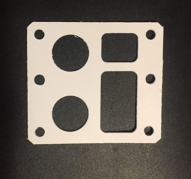
Figure 4
Result and Evaluation
The gasket was well aligned along the sides (Figure 5), but overall it shifted down, but nonetheless, it managed to fit in the 2 holes at the side (Figure 6). There are several reasons as to why this mistake occurred. Firstly, it could be because of how I measured the distance between each holes. I measured them from the outside edge, and not the inside edges. A way to improve this could be to take both the inner and outer edge dimensions, and ensure the calculations for both matched up. Secondly, I used 2 different sets of calipers to take the measurements because of some technical error that occurred in class. The calibration of both calipers could be different, and I did feel a different ‘touch’ to both calipers. Furthermore, the dimension of the mini rectangular block were just slightly different perhaps due to wear and tear, and although I did take that into account when doing the new measurements, it increases the possibility of human error. To improve this, I should have done my best to only use the same caliper for all the measurements to keep it constant. Lastly, while measuring, I kept shifting the surface on which I was placing the block on. I shifted between laying it/placing it on my file and on the table. An improvement to this was perhaps it would be better to measure on the same flat surface throughout, i.e. the table.
This assignment really showcased the importance of dimensions and that even a slight variation could skew the entire project off-course.


Figure 6
Figure 5